You are using an out of date browser. It may not display this or other websites correctly.
You should upgrade or use an alternative browser.
You should upgrade or use an alternative browser.
Another (another) SS TIE Bomber
- Thread starter thibkaji
- Start date
thibkaji
Well-Known Member
Welp, I’m sitting at the airport bar waiting on my flight and thought, how about another mini-update? So here goes…
I took a stab at the back panel on the center block. The layout from moska’s parts diagram doesn’t quite align with what I’m seeing in the reference, so I opted for the reference!
As you can see, the right tab that sticks out from the Sd.Ah.52 (green part) should pretty much be centered to the Shinano parts on the top, which itself is pretty much centered on the top of the center block. Also, the distance between the left tab to the fuselage is much smaller than on the diagram. This means the part should be attached further to the left.


Based on that configuration, I ended up with this alignment for the back panel:

I’ll double-check those dimensions once I’ve got the armature positioning set, but this should be pretty close.
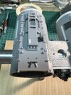
The last thing I’ve got an update for is attaching some components to the top of the cockpit fuselage.
I cut and sanded the Flak 36/37 part that goes in the side at an angle so it would fit properly:


Then I went to grab the small Flak 36/37 part that goes between the front nibs and it was broken! One side was missing! So, I did what anyone would do — measured the diameter of the existing half, and made a new one from styrene rod:

Good enough for government work!

Last part I’ve attached (for now) is the Mörser Karl part that’s all over this kit. If you look at the reference, the part needs to be sanded on an angle to meet up nice and flush to the angled front of that Leopold part:

A near perfect fit! A little glue and that’ll melt on flush.

Well, that’s about it for now. I had messed up my fuselage tubes due to some mis-measurements and thought I was going to have to make new ones, but mjhenks threw in some new tubes with the armature I got from him, so I’m back in business. In the meantime I’d cut some spare tubing to size without the ribbing just to test fit and get an idea for sizing, so here are a few rough assembly pics showing the new armature, temp tubes, and some of the assemblies I’ve posted about.


It’s really starting to shape up!
Next up — getting the new tubes cut to the armature, mounted, and start scribing the new tubes! Til next time!
I took a stab at the back panel on the center block. The layout from moska’s parts diagram doesn’t quite align with what I’m seeing in the reference, so I opted for the reference!
As you can see, the right tab that sticks out from the Sd.Ah.52 (green part) should pretty much be centered to the Shinano parts on the top, which itself is pretty much centered on the top of the center block. Also, the distance between the left tab to the fuselage is much smaller than on the diagram. This means the part should be attached further to the left.
Based on that configuration, I ended up with this alignment for the back panel:
I’ll double-check those dimensions once I’ve got the armature positioning set, but this should be pretty close.
The last thing I’ve got an update for is attaching some components to the top of the cockpit fuselage.
I cut and sanded the Flak 36/37 part that goes in the side at an angle so it would fit properly:
Then I went to grab the small Flak 36/37 part that goes between the front nibs and it was broken! One side was missing! So, I did what anyone would do — measured the diameter of the existing half, and made a new one from styrene rod:
Good enough for government work!
Last part I’ve attached (for now) is the Mörser Karl part that’s all over this kit. If you look at the reference, the part needs to be sanded on an angle to meet up nice and flush to the angled front of that Leopold part:
A near perfect fit! A little glue and that’ll melt on flush.
Well, that’s about it for now. I had messed up my fuselage tubes due to some mis-measurements and thought I was going to have to make new ones, but mjhenks threw in some new tubes with the armature I got from him, so I’m back in business. In the meantime I’d cut some spare tubing to size without the ribbing just to test fit and get an idea for sizing, so here are a few rough assembly pics showing the new armature, temp tubes, and some of the assemblies I’ve posted about.
It’s really starting to shape up!
Next up — getting the new tubes cut to the armature, mounted, and start scribing the new tubes! Til next time!
It's crazy to watch someone go through the same journey I just went through. I look at your in progress pics and then look at my finished model in disbelief. I'm simultaneously in awe at the fact that mine was once in the current state as yours and excited for what lies ahead for you.
stevielewis
Sr Member
Fantastic work! ")
thibkaji
Well-Known Member
I can only imagine! Your build has been of infinite assistance to mine, pointing out pitfalls and things to pay attention to. I’m just hoping to add to that any way I can. I also see how yours finished, and am just hoping I’m able to get half as good of a result with mine.It's crazy to watch someone go through the same journey I just went through. I look at your in progress pics and then look at my finished model in disbelief. I'm simultaneously in awe at the fact that mine was once in the current state as yours and excited for what lies ahead for you.
thibkaji
Well-Known Member
Back on the bench!
New tubes have been drilled out and cut to fit around the armature. My first set of tubes I used a cutting blade and small saw blade to cut out the boxes, but I took a different approach this time around. I chose to use Dymo tape to mark the line I needed to cut, then used my old Tamiya scribing tool to cut through the tube and get a very straight line:

Did that twice, made sure the tubes were centered to the armature, and I think it’s looking pretty good!


With that out of the way, decided it was time to scribe panels onto the tubes. I used the references and Moska’s parts map to transfer the locations of the panel lines over to the fuselages. Once there with pencil, I checked the locations using kit parts and adjusted as needed. To scribe the lines, I again used Dymo tape to create a nice straight line. I also used a different scribe tool to cut the grooves — the Tamiya engraving blade holder with a .25mm wide cutting blade. This allowed for very fine control over the blade, and the Dymo tape ensures the cut line is straight.

And the results:


I also want to call out these specific panel lines on the sides of the fuselages around the Harrier parts. It’s hard to see on the some of the references out there, but are present on both sides.


Those scribed sides on the filming model:

And with that out of the way, I mounted the tubes back onto the armature and used 2-part epoxy resin to secure them in place. They’re not going anywhere!
I have now finally reached the eagerly-anticipated point where I can start mounting kit parts!!
Had a go with the bomb-side fuselage first. Haven’t gotten too far, but attached some parts on the top:

I also attached some strips of styrene along the fuselages where appropriate:

Test fitting some more parts. Very satisfying to attach these components and see this thing start to come to life!

Rear panel installed:

Attached the Saturn V rings that go in the back. I’ll attach the other Saturn V parts once I get in some red 3mm LEDs and wire them up. Not planning to light this thing, but want the wiring in there for accuracy.


And that’s where I’ll leave it for now. Next update should be attaching the rest of the parts on top and bottom of the fuselages, and wiring up the Saturn V/LEDs for the back. Things are moving, and I can see the finish line ahead!
TIL next time, keep in scratchin’!
New tubes have been drilled out and cut to fit around the armature. My first set of tubes I used a cutting blade and small saw blade to cut out the boxes, but I took a different approach this time around. I chose to use Dymo tape to mark the line I needed to cut, then used my old Tamiya scribing tool to cut through the tube and get a very straight line:
Did that twice, made sure the tubes were centered to the armature, and I think it’s looking pretty good!
With that out of the way, decided it was time to scribe panels onto the tubes. I used the references and Moska’s parts map to transfer the locations of the panel lines over to the fuselages. Once there with pencil, I checked the locations using kit parts and adjusted as needed. To scribe the lines, I again used Dymo tape to create a nice straight line. I also used a different scribe tool to cut the grooves — the Tamiya engraving blade holder with a .25mm wide cutting blade. This allowed for very fine control over the blade, and the Dymo tape ensures the cut line is straight.
And the results:
I also want to call out these specific panel lines on the sides of the fuselages around the Harrier parts. It’s hard to see on the some of the references out there, but are present on both sides.
Those scribed sides on the filming model:
And with that out of the way, I mounted the tubes back onto the armature and used 2-part epoxy resin to secure them in place. They’re not going anywhere!
I have now finally reached the eagerly-anticipated point where I can start mounting kit parts!!
Had a go with the bomb-side fuselage first. Haven’t gotten too far, but attached some parts on the top:
I also attached some strips of styrene along the fuselages where appropriate:
Test fitting some more parts. Very satisfying to attach these components and see this thing start to come to life!
Rear panel installed:
Attached the Saturn V rings that go in the back. I’ll attach the other Saturn V parts once I get in some red 3mm LEDs and wire them up. Not planning to light this thing, but want the wiring in there for accuracy.
And that’s where I’ll leave it for now. Next update should be attaching the rest of the parts on top and bottom of the fuselages, and wiring up the Saturn V/LEDs for the back. Things are moving, and I can see the finish line ahead!
TIL next time, keep in scratchin’!
Quite the update. Great images of the scribe lines. You say you used more than one scribe tool. Are you suggesting the scribe marks are different widths or that some tools were easier to get the job done with?
What are the three small white lines in your 13th picture? It is of the bottom showing the white styrene strip.
What are the three small white lines in your 13th picture? It is of the bottom showing the white styrene strip.
You are KILLING it, my friend!
thibkaji
Well-Known Member
Those are actually where I accidentally over-scribed a few lines. They weren’t supposed to extend that far on the bottom there, so I filled them with putty.Quite the update. Great images of the scribe lines. You say you used more than one scribe tool. Are you suggesting the scribe marks are different widths or that some tools were easier to get the job done with?
What are the three small white lines in your 13th picture? It is of the bottom showing the white styrene strip.
As for tools, for basic cutting of the opening on the tubes to fit around the armature the standard Tamiya scriber was used. For all of the panel lines I used the engraving tool with .25mm blade. One other thing I did do but didn’t mention (I’ll go back and edit) was go back over the scribed lines with the Tamiya scriber to add a bit of an angle to the grooves. They felt too squared off so one pass with the scriber, which has a v-shaped blade, helped angle out the top edges just a bit.
So, all the scribed lines for me were the same width, just used both tools to get the job done. YMMV
thibkaji
Well-Known Member
So I scribed those for nothing?! Ah, man!!Your build's looking great. If you don't mind a little constructive criticism?
These panels are raised.
View attachment 1850976View attachment 1850977
I never mind constructive criticism! Anything feedback that makes my build better and more accurate is welcome! Especially from you, good sir!
None of the references I have showed a clear enough angle to indicate those were raised, so I mistakenly thought they were scribed. Easy enough to fix! Thanks for pointing that out, I’ll make the necessary changes.
Incredible progress, I'm living the build. I am stalled on mine. work is hectic af
thibkaji
Well-Known Member
Time for another update. I said before that things are moving, and I feel like I made a huge leap over the last week. The base crust is set, and now it's just adding on all the toppings! Let's go!
First things first -- addressing the scribed markings on the bottom of the bomb fuselage that should be raised panels. Cut some thin styrene sheet stock to size and glued those on right over top of the scribed section. Covered it well, and should now be correct. ^_^

Next, I went after the Harrier ejector seat part that mounts to the sides of the fuselages. I glues a piece of 1mm styrene sheeting to the bottom of the part to beef it up a bit. I needs a bit more than the part has in order to be sized properly when attached.


Trimmed to size:

I then worked on modifying the front end to curve it down like it is on the bomber, and sanded the back end around the 3/4" tube to get it shaped properly for where it meats up with the wing tube supports. At this point I felt it was time to mold the part, so I made a mold and cast a resin copy:

After that, it was just a matter of sanding down the underside to conform to the fuselage:

And then stick it on. It fits really well, I am delighted!

Here it is with the backside Leopold A7 part attached along the tube. Note that you have to cut the cross-brace off the backside of that part and shorten it a bit in order to make it both fit around the harrier parts' extended "fins" and be even with the frontside part.

And the other side:

Next component I went after is the Yamato (old tooling) part that attaches to the underside. This is the only Yamato part on the model, and has the only Sd.Ah.51 part, as well. So, I attached those two components together as shown here:


And then sanded the underside to conform to the bottom of the fuselage.

And mounted:

I then attached the 25 pounder part to the back of the Yamato part, as shown:

BUT! This is the wrong position! I was using Moska's parts guide for this, and the above placement lines up with that diagram:

However, the actual filiming model shows this as being mounted further around, basically centered on the Yamato part:

So I moved it around the correct position:

Whew! That's better!
Next I went after the A7 Leopold parts mounted onto the top/bottom of the cockpit fuselage. In a previous post I shared how I added the various components to one of these parts -- now we get to attach it!
First thing's first -- I needed two of those girder parts that donate their bent ends to the wing pylons, which go underneath the top/bottom Leopold parts. I only had two Leopold kits, and used up both on those wing pylons, so I decided to get creative! I decided to just glue together a few remnants from those Leopold parts with the other non-bent girder parts from the kit, giving me a part that pretty close, but a match for what you can actually see on the kit.

And mounted on the top.

You may notice that there are some filled scribe lines with new ones located about 1 mm to the side. When I was fitting this part to the top and checking for proper positioning, I found that it was skewing closer to one of the scribed panel lines when centered properly on top instead of centered between them (see below). I determined my positioning of the panel lines was off, so I filled them and cut new ones. If I can offer some advice here -- dry-fit your parts after you've mounted your fuselage tubes to the armature to ensure they actually fall where you expect them -- then scribe your lines. I was very close on mine, but off just a small amount in this area. You live and learn!

And on the bottom:

And here it is with the large Leopold part from my prior post mounted.

You'll probably notice that there's a small gap on the side there -- I could not for the life of me get this part to lay down so both sides of that top were flush to the fuselage. I wasn't that concerned with the gap along the sides, as those would mostly be covered with other parts (coming up next), but it did leave a small gap along the front side that would be visible. I'll fill that with some putty and sand flush before I mount the cockpit.

And here the gaps are now covered using those additional parts:


Rinse and repeat for the bottom:

Last components added to those Leopold parts on top/bottom are the parts from the Stuka (I do have one Morser Karl part that needs to be attached to the bottom part, but I keep forgetting to do it). Here's an unmodified part with the modified part:

And attached, paying close attention to the orientation of the part from the references:

I next addressed a few odds and ends.
Parts mounted to the center block on front:


Bomb Chute attached:


Took care of one of the "strut" components along the wing tubes -- others should be done by end of this week:

And finally, mounted red LEDs to the rear fuselage "engines" and attached those to the fuselage backs. I did connect some wiring up to the leds, but it's not functional -- it's more to complete the look of seeing wiring if you look through the front of the cockpit.


And I think that's where I am now. That was a HUGE update! Got a lot more done, it's flying by now. I think I might have another week or two of fiddling around to get parts attached and fine-tuned, and then it'll be time for primer. Feels surreal to be honest. I'll leave you all with a few current overall progress pics until I can get back to this. Til next time, keep on scratchin'!


First things first -- addressing the scribed markings on the bottom of the bomb fuselage that should be raised panels. Cut some thin styrene sheet stock to size and glued those on right over top of the scribed section. Covered it well, and should now be correct. ^_^
Next, I went after the Harrier ejector seat part that mounts to the sides of the fuselages. I glues a piece of 1mm styrene sheeting to the bottom of the part to beef it up a bit. I needs a bit more than the part has in order to be sized properly when attached.
Trimmed to size:
I then worked on modifying the front end to curve it down like it is on the bomber, and sanded the back end around the 3/4" tube to get it shaped properly for where it meats up with the wing tube supports. At this point I felt it was time to mold the part, so I made a mold and cast a resin copy:
After that, it was just a matter of sanding down the underside to conform to the fuselage:
And then stick it on. It fits really well, I am delighted!
Here it is with the backside Leopold A7 part attached along the tube. Note that you have to cut the cross-brace off the backside of that part and shorten it a bit in order to make it both fit around the harrier parts' extended "fins" and be even with the frontside part.
And the other side:
Next component I went after is the Yamato (old tooling) part that attaches to the underside. This is the only Yamato part on the model, and has the only Sd.Ah.51 part, as well. So, I attached those two components together as shown here:
And then sanded the underside to conform to the bottom of the fuselage.
And mounted:
I then attached the 25 pounder part to the back of the Yamato part, as shown:
BUT! This is the wrong position! I was using Moska's parts guide for this, and the above placement lines up with that diagram:
However, the actual filiming model shows this as being mounted further around, basically centered on the Yamato part:
So I moved it around the correct position:
Whew! That's better!
Next I went after the A7 Leopold parts mounted onto the top/bottom of the cockpit fuselage. In a previous post I shared how I added the various components to one of these parts -- now we get to attach it!
First thing's first -- I needed two of those girder parts that donate their bent ends to the wing pylons, which go underneath the top/bottom Leopold parts. I only had two Leopold kits, and used up both on those wing pylons, so I decided to get creative! I decided to just glue together a few remnants from those Leopold parts with the other non-bent girder parts from the kit, giving me a part that pretty close, but a match for what you can actually see on the kit.
And mounted on the top.
You may notice that there are some filled scribe lines with new ones located about 1 mm to the side. When I was fitting this part to the top and checking for proper positioning, I found that it was skewing closer to one of the scribed panel lines when centered properly on top instead of centered between them (see below). I determined my positioning of the panel lines was off, so I filled them and cut new ones. If I can offer some advice here -- dry-fit your parts after you've mounted your fuselage tubes to the armature to ensure they actually fall where you expect them -- then scribe your lines. I was very close on mine, but off just a small amount in this area. You live and learn!
And on the bottom:
And here it is with the large Leopold part from my prior post mounted.
You'll probably notice that there's a small gap on the side there -- I could not for the life of me get this part to lay down so both sides of that top were flush to the fuselage. I wasn't that concerned with the gap along the sides, as those would mostly be covered with other parts (coming up next), but it did leave a small gap along the front side that would be visible. I'll fill that with some putty and sand flush before I mount the cockpit.
And here the gaps are now covered using those additional parts:
Rinse and repeat for the bottom:
Last components added to those Leopold parts on top/bottom are the parts from the Stuka (I do have one Morser Karl part that needs to be attached to the bottom part, but I keep forgetting to do it). Here's an unmodified part with the modified part:
And attached, paying close attention to the orientation of the part from the references:
I next addressed a few odds and ends.
Parts mounted to the center block on front:
Bomb Chute attached:
Took care of one of the "strut" components along the wing tubes -- others should be done by end of this week:
And finally, mounted red LEDs to the rear fuselage "engines" and attached those to the fuselage backs. I did connect some wiring up to the leds, but it's not functional -- it's more to complete the look of seeing wiring if you look through the front of the cockpit.
And I think that's where I am now. That was a HUGE update! Got a lot more done, it's flying by now. I think I might have another week or two of fiddling around to get parts attached and fine-tuned, and then it'll be time for primer. Feels surreal to be honest. I'll leave you all with a few current overall progress pics until I can get back to this. Til next time, keep on scratchin'!
Attachments
stevielewis
Sr Member
Great update! Your build is looking wonderful.
Fantastic work!
Especially outstanding scribing.
If you don't mind my asking, it would be great if you'd document the upcoming process of applying the pencil lines and dots to this beauty.
I've followed almost every bomber build on this forum and that part is usually not well documented.
Keep it up!
Especially outstanding scribing.
If you don't mind my asking, it would be great if you'd document the upcoming process of applying the pencil lines and dots to this beauty.
I've followed almost every bomber build on this forum and that part is usually not well documented.
Keep it up!
Last edited:
Similar threads
- Replies
- 56
- Views
- 8,555
- Replies
- 114
- Views
- 11,907