You are using an out of date browser. It may not display this or other websites correctly.
You should upgrade or use an alternative browser.
You should upgrade or use an alternative browser.
Open Source Studio Scale TIE Fighter Thread
- Thread starter MrRobot
- Start date
-
- Tags
- opensource tie fighter
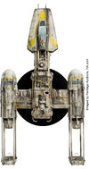
Seeking some help with Y-Wing reference (yes you read that right—Y-Wing!). This little subassembly figured below appears in the TIE Fighter cockpit ceiling. As you can imagine, cockpit ceiling ref isn't great. But if you can reliably work out the dimensions of this bit you can get some really solid constraints for the dimensions of the cockpit ceiling panels:


The image above is OK, but perhaps just a wee bit hazy for reliable back-calculation of the measurements.
If anyone has higher res images they're willing to share, I would be in your debt! As always, I will not distribute or re-post any images you share with me unless you give me permission.
The image above is OK, but perhaps just a wee bit hazy for reliable back-calculation of the measurements.
If anyone has higher res images they're willing to share, I would be in your debt! As always, I will not distribute or re-post any images you share with me unless you give me permission.
I believe that is made up of 3 parts all laid on top of each other. That's all I have without looking at my scans. Sorry
Cheers. Yep, the top two parts I've got worked out (1/12 M23 and 1/35 Nichimo *Tiger). I'm not clear whether the main panel is scratch-built or not. However, my main concern is just an image good enough for working out the dimensions based on the known parts.I believe that is made up of 3 parts all laid on top of each other. That's all I have without looking at my scans. Sorry
Ok sounds good I'll check my ref photos and send you what i have tonightCheers. Yep, the top two parts I've got worked out (1/12 M23 and 1/35 Nichimo *Tiger). I'm not clear whether the main panel is scratch-built or not. However, my main concern is just an image good enough for working out the dimensions based on the known parts.
I can't find my ref, but looking at kit scans i want to airfix Mauritania maybe
Thanks! That picture is still very helpful. While the piece itself is missing, I can still constrain its size from the surrounding parts.It seems that it was a cover to hide the hole. The image quality of this photo is good, but unfortunately the key parts are missing.
I can't find my ref, but looking at kit scans i want to airfix Mauritania maybe
Which part from the Mauritania do you think? I didn't see anything in a quick check, but I do see some of the skylights(?) from the Mauretania were used on the Y-Wing. It's possible one of them is the same dimensions.
Major milestone reached on parts IDs. Have now more or less finished the exterior parts maps for the TIE Fighter which I've posted over at SciFiKitbash. Thanks to DAR23 and Shamon for some recent inputs! Only one part doesn't have an ID (apart from some grab handles that can't really be worked out until a build starts to happen). Part #2 in the map below:

Here's an extra reference:

Once again, none of this is to say all the ID's are right. There's simply an annotation to each part now and most seem to be reasonably good. Some are pretty unequivocal. Others can be a bit more challenging. As always, inputs are more than welcome.
Here's an extra reference:
Once again, none of this is to say all the ID's are right. There's simply an annotation to each part now and most seem to be reasonably good. Some are pretty unequivocal. Others can be a bit more challenging. As always, inputs are more than welcome.
Very helpful! Thank you!
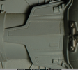
A couple of thoughts on that picture:
Comparing with what little I can see in the TIE cockpit ceiling, the subassembly here on the Y-Wing looks to have been cut down a bit to fit the hull. Relative to this view, the height (vertical axis in picture) appears to be unaffected. However, the width (horizontal axis) is trimmed a bit. That's OK, because the vertical axis corresponds to the width of the ceiling panel in the TIE.
Oddly, the modifications seen in the grayscale picture above do not seem to have been present in the colour photo. These were done sometime after the colour photo was taken.
Having seen this close-up, I'll buy that the base plate of the sub-assembly was scratch-built with little chipping details added. However, the bent pipe thing on it is harder to make out. Looks like it could be a tool from an armor kit or a bit of landing gear. Hard to say.
Not a lot of build progress due to work, but now that things are settling down again I got the chance to work on the pylons. I've been puzzling over these for the last few months because the geometry is not easy to work out from reference alone. A shout-out to chazzychaz for sending me some measurements off his AMT TIE Fighter, which I used to check my measurements (rescaled) and things seem to check out.
Here's the main pylon roughed out.

And here are the strut parts temporarily added into place:

These all need some tidying up, but this is what I had time for today. I'll probably redo the strut parts that go top and bottom. For reasons I'll outline below, it's imperative that you get the measurements and geometry of these right. Once I'm happy with what I've got, I'll create a table of measurements and add it to the OP.
The first thing you might ask is: "why are you making the pylon as a single piece?" rather than making separate top and bottom halves and marrying them up along the hinge lines? Indeed, in an earlier effort I did just that. It turns out, I think the ILM model shop guys did them as one piece. These were then cast and cut in various ways to make top and bottom pylon halves, as well as the end pylons.
For one, if you look at references, the mould seam doesn't actually line on the apex of the pylon, it's often just a little bit off:


Instead, I think one master pylon was made, including 'top' and 'bottom' halves. This was cast, cut, and detailed in different ways depending on the component. The main one was made to fit the hull sphere, of course. Then, as is widely known, the terminal pylon was made by cutting the end off the main pylon.
What seems less widely known is that the leftover from that cut can be used to make the end plate for the wing. This is something I only just noticed in the last week:

While I'm building my TIE using mostly "traditional" methods, I do use Blender to test out measurements and prototype components. Here's a quick screen grab to show the three pieces together:

Indeed, if you look carefully at images of the end plate, you can even see the longitudinal grooves that you see on the main pylon (and to a lesser extend on the terminal pylon):

If you're going to do it the same way, then you need to get all the measurements very close to right, otherwise your end plate will look funny. The upshot is that this will help ensure that your terminal pylon and end plate have very similar footprints. This is important because they need to fit snugly between the greeblies on the wingstar hub and you want them to therefore have the same geometry. This is likely why the ILMers did it—they were clever like that!
Here's the main pylon roughed out.
And here are the strut parts temporarily added into place:
These all need some tidying up, but this is what I had time for today. I'll probably redo the strut parts that go top and bottom. For reasons I'll outline below, it's imperative that you get the measurements and geometry of these right. Once I'm happy with what I've got, I'll create a table of measurements and add it to the OP.
The first thing you might ask is: "why are you making the pylon as a single piece?" rather than making separate top and bottom halves and marrying them up along the hinge lines? Indeed, in an earlier effort I did just that. It turns out, I think the ILM model shop guys did them as one piece. These were then cast and cut in various ways to make top and bottom pylon halves, as well as the end pylons.
For one, if you look at references, the mould seam doesn't actually line on the apex of the pylon, it's often just a little bit off:
Instead, I think one master pylon was made, including 'top' and 'bottom' halves. This was cast, cut, and detailed in different ways depending on the component. The main one was made to fit the hull sphere, of course. Then, as is widely known, the terminal pylon was made by cutting the end off the main pylon.
What seems less widely known is that the leftover from that cut can be used to make the end plate for the wing. This is something I only just noticed in the last week:
While I'm building my TIE using mostly "traditional" methods, I do use Blender to test out measurements and prototype components. Here's a quick screen grab to show the three pieces together:
Indeed, if you look carefully at images of the end plate, you can even see the longitudinal grooves that you see on the main pylon (and to a lesser extend on the terminal pylon):
If you're going to do it the same way, then you need to get all the measurements very close to right, otherwise your end plate will look funny. The upshot is that this will help ensure that your terminal pylon and end plate have very similar footprints. This is important because they need to fit snugly between the greeblies on the wingstar hub and you want them to therefore have the same geometry. This is likely why the ILMers did it—they were clever like that!
Attachments
FYI: I've started an interest thread in the Project Runs for casting sets of TIE greeblies.
I'm going to start work this month on my master wingstar pattern with the hopes of having it ready for casting by the end of next month (fingers crossed!). I've got all of the parts I need to do the the job.
I've created my blueprint with the help of pyro parts from the Propstore site. These marry up really well and they have scale references included, which really helps. On top of this, we know the diameter of the hole (1.25") so we can also use that as a reference. I composited these in Illustrator:

I will clean up my Illustrator file and post it here, but happy to provide it to anyone who wants the "rough" version.
It has been pointed out before how close the eFX TIE wing is to the Gawley blueprint, which suggests it was followed pretty closely. Using these refs, it's actually a dead-ringer. I'd bet dollars to doughnuts the ILMers cut the wing pattern right off the blueprint:

The one thing I'm trying to sort out now is the thickness. I'm going to use 2mm plastic sheeting for the main panel.
Does anyone know how thick the raised hub is? I've worked it out trigonometrically to be about 8mm. But there's probably ±1mm error on that.

There's a practical reason I'm concerned about that 1mm error that goes beyond membership in the International Pathological Perfectionists' Union. The proximal ends of the wingstar struts are nearly the same height as the hub. At one point, there's a greebly that overhangs the strut:

I've measure the parts stuck together and they give about a 3.2mm clearance for strut to pass under.
Assuming (naively) an even taper for the strut from the hub to its end, then my strut tapers out too 'quickly' for this greebly combo to work. So, to narrow down the variables, I'll need to find out more precisely how thick the wingstar hub is.
Any help here?
I've created my blueprint with the help of pyro parts from the Propstore site. These marry up really well and they have scale references included, which really helps. On top of this, we know the diameter of the hole (1.25") so we can also use that as a reference. I composited these in Illustrator:
I will clean up my Illustrator file and post it here, but happy to provide it to anyone who wants the "rough" version.
It has been pointed out before how close the eFX TIE wing is to the Gawley blueprint, which suggests it was followed pretty closely. Using these refs, it's actually a dead-ringer. I'd bet dollars to doughnuts the ILMers cut the wing pattern right off the blueprint:
The one thing I'm trying to sort out now is the thickness. I'm going to use 2mm plastic sheeting for the main panel.
Does anyone know how thick the raised hub is? I've worked it out trigonometrically to be about 8mm. But there's probably ±1mm error on that.
There's a practical reason I'm concerned about that 1mm error that goes beyond membership in the International Pathological Perfectionists' Union. The proximal ends of the wingstar struts are nearly the same height as the hub. At one point, there's a greebly that overhangs the strut:
I've measure the parts stuck together and they give about a 3.2mm clearance for strut to pass under.
Assuming (naively) an even taper for the strut from the hub to its end, then my strut tapers out too 'quickly' for this greebly combo to work. So, to narrow down the variables, I'll need to find out more precisely how thick the wingstar hub is.
Any help here?
Does anyone know how thick the raised hub is? I've worked it out trigonometrically to be about 8mm. But there's probably ±1mm error on that.
View attachment 1950721
The answer here is 6.35mm which is 1/4". Thanks swgeek! This checks out with the greebly combo (which was predicting a 6.4mm thickness from my blueprints).
Similar threads
- Replies
- 114
- Views
- 11,998