YAFF - Yet Another 5 Footer Falcon Build

Dazza007,
Just caught up with the past month and a half on your thread. Really talented engineering applied as well as printing (that I know nothing about). Incredible detail that seems to perfectly match kit parts. No doubt your no stranger to the importance of side wall height cautioned by the experts above. My beginner‘s, most important advice, is the same.

Using kit part words to explain this: The Pontoon Bridge height is critical for the mandible as it measures the “channel“ and that does not include skin/armor thickness. The disk side walls are another height to get right based on greeblies that must be inserted. My biggest adjustment discovery rework was at the side wall height of the Sheridan. That jaw box mouth is set back as you know from the front of the tip of the disc edge curve. That means the “channel“ height is the greatest of the three. It sets the gap for the Duster greeblie discussed by Studio Kitbash as the disc skin/armor slopes down to the top of the mandible skin. Again, overall height and “channel” height are not the same.

Your computer skill will certainly support your build as a auto pilot once factored in. I, unfortunately, use a ruler & jigs to learn this and it’s a lesson that keeps on giving.

Great work.
 
Voice of experience speaks.
Yes, that was part of the design - basically all of the pit wells occur within my middle support ring, so I have two support spacers, one half height for areas that need to be shown under the skin.
if there is a pit I will use the half height one and pad it out around the pit itself.
(I'm hoping that makes sense)
spacers.png
 
As I said before: a wonderful piece of engineering taking shape in front of our eyes (y) (y) :cool: :cool: :notworthy: :notworthy:
And at 7kg; not feather weight categoryo_O Thank the Maker that most of the inner core is hollowed!
 
The only hassle with doing such a big print, is the waiting for prints - but at least I have my central frame completed - I am now printing the curved sections as well as trying some other parts as I go. (And yes I know the proper studio scale doesn't have landing gear, mine will have gear and a loading ramp that can be swapped for open or closed)

IMG_20220528_102158.jpg


?hash=67a64fd04a8c025a2d016d1d96b1fc4c.jpg
IMG_20220528_102717.jpg
 

Attachments

  • IMG_20220528_102622.jpg
    IMG_20220528_102622.jpg
    2.4 MB · Views: 102
That's a lot of plastic. Awesome Daz!

Hey, don't forget the 5'falcon was retrofitted with landing gear for Empire Strikes Back for the Bespin landing scene.

11079661_872023239529356_3759508254651615270_n.jpeg


The references that you are using for your legs are very much the same as what was seen on the model.

10365993_706384852759863_4763547806254957919_n (1).jpeg


The gear doors are still in place covering the wells but unsure if the legs are inside, in the archive, a private collection or lost to time.

There was a Propstore auction many years ago for a leg or casting of the leg that was apparently from the production.
img04.jpg


Not sure about the ramp though...
 
Dazza007,

Really impressive structural engineering work. Another “deviant” from true Studio Scale (like me), but glad to see you factoring in landing gear and ramp. They are such a unique part of the overall incredible Falcon design. Replacement components are the way to go as you are planning.

I shake my head out of respect every time I see the CAD and printing work you guys produce on this site. One needs another life time to learn this technology and then develop those skills. Great work.
 
Thanks all for the feedback and info - I like the word 'Deviant' - so am going to call it that from now on -
I'm a little lost when it comes to the Landing gear doors, I do have a few options from around the place. Will post some photos once I print the complete well insert.
Thanks Bjorn for the photos - Looks like i do have a few tweaks to make
 
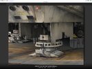
OK Looking further into the ESB Landing gear - of which there is not a lot of reference around. I have found what I think is my major problem.
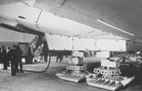
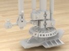
I am trying to make the landing feet and rings fit into the landing well/cavity - it looks like there may have been a lot of poetic/spatial licence in the design here with the feet a lot wider than the actual docking well.
three.png

I also noticed in the actual bespin landing, that there was quite a difference between the hydraulic extension of the gear in flight, vs landed with the weight on - extending by the suspension range shown above within the 2 horizontal lines. - I might consider implementing some extension in this range as well, just for fun.
two.png


It also looks like the original ESB landing had the landing gear doors angled and hinged similar to the Bandai Model - but very hard to tell from these shots
098.png


Any further info or shots anyone has of the ESB landing gear I would be extremely grateful
 
Dazza007,
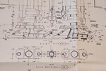
As an X-aircraft mechanic, I had to stray from true Studio Scale and have landing gear on my Falcon. Interesting you also noticed big feet vs. wheel well door size. Mine are retractable so size matters in stead of the plug in versions. My gear design is per drawings. There seems to be many different types of feet designs, hydraulics, L/G door styles etc. among models and pictures. Bottom view’s of the door openings still confuse me, so no decision made there yet. The ”hinged / angled doors” are neat, however they are complex.

Attached are some web site grabs I found to be interesting regarding door design. No doubt you have likely seen these, but the show the variety
 

Attachments

  • B85F2C8A-7D9A-4DBD-8CFD-DAE53199BB6B.jpeg
    B85F2C8A-7D9A-4DBD-8CFD-DAE53199BB6B.jpeg
    76.8 KB · Views: 171
  • 906CE298-73E6-4602-85CE-70164C670EEC.jpeg
    906CE298-73E6-4602-85CE-70164C670EEC.jpeg
    555.7 KB · Views: 149
  • E53DBF4A-F448-4B04-B4D1-80C2F8DCEA71.jpeg
    E53DBF4A-F448-4B04-B4D1-80C2F8DCEA71.jpeg
    148.3 KB · Views: 144
  • AB5D3B8A-367A-4637-84D3-C62DDCE1F0C2.jpeg
    AB5D3B8A-367A-4637-84D3-C62DDCE1F0C2.jpeg
    9 MB · Views: 156
  • 282EF9B2-AD54-4B10-8998-63BA1B03DC72.jpeg
    282EF9B2-AD54-4B10-8998-63BA1B03DC72.jpeg
    74.3 KB · Views: 151
  • 88093DC1-A94A-42BE-AA50-0D14DCA30ADF.jpeg
    88093DC1-A94A-42BE-AA50-0D14DCA30ADF.jpeg
    46.6 KB · Views: 151
Dazza007,
As an X-aircraft mechanic, I had to stray from true Studio Scale and have landing gear on my Falcon. Interesting you also noticed big feet vs. wheel well door size. Mine are retractable so size matters in stead of the plug in versions. My gear design is per drawings. There seems to be many different types of feet designs, hydraulics, L/G door styles etc. among models and pictures. Bottom view’s of the door openings still confuse me, so no decision made there yet. The ”hinged / angled doors” are neat, however they are complex.

Attached are some web site grabs I found to be interesting regarding door design. No doubt you have likely seen these, but the show the variety
Thanks Searun,
My current design is like yours, based on the blueprints with largish flat doors similar to the Disney one , I am possibly overthinking things, will more than likely just stick with what I have, but would be nice to add the spring hydraulic landing system to that. (I have so much more that needs to be done anyway.

Cheers Darrin
 
Yea, though I'd prefer mine to be in a finished dome instead of my box of parts.

Another unfinished project :rolleyes:
 
Yea, though I'd prefer mine to be in a finished dome instead of my box of parts.

Another unfinished project :rolleyes:
Those are reject parts, true my r2 is waiting on painting and some electronic parts (but I'll be waiting a while for motor controller boards, so its on hold until then) but the printing etc is now completed.
Actually just waiting on the astropixels lighting kit for the dome, should be here any day - might distract me from the falcon for a few days then

IMG_20220124_161006.jpg
 
Last edited:
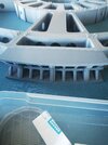
Well coming up to the 3 month mark and have just finished printing the upper half of the hull frame, just printing the cavity inserts for the Radar Dish and inspection panels areas. (That'll be the next photo) - Excuse the mess...
Its only half glued, this is mostly just a dry fit

IMG_20220609_122820.jpg
IMG_20220609_123208.jpg
 
Back
Top