June 30, 2024
I just got back from a weekend at the Oregon coast and thought I'd do this update there. But, alas, there was too much fun to be had.
The wing supports/stabilizers are made from the Leopold parts C8 and C10. Which one depends on whether it's on the top or the bottom.
This needed to be cut down considerably. I left some "fat" on the part so I, again, could sneak up on the fit.
The easiest way I could figure to get the piece to match the curvature of the body was to trace the shape onto the the part using a my sanding jig and then slowly start sanding it to match the curve, adjusting as I went along.
The front and rear stabilizers were made from four Leopold A7 parts that were cut down. These were pretty straight forward. Once the piece the was needed was cut out from the part then it was a matter of sanding it to conform to the shape of the armature. I did this by taping some sandpaper around one side of the armature and slowly sanding it to shape. Sorry no pics of that.
From there I moved onto the engines. This involved cutting down two Saturn V sections, parts 28 and 29 glued together, and then sawing out a section to create a truncated cone. The height is 8.5mm-ish. I measured the diameter of the cone section and marked it just over 2" so I had some room to sneak up on the correct diameter as I sanded it. I cut the section out using a razor saw.
Using part 61 as a makeshift brace/grip I sanded the ring down to the correct diameter that matched the body tube and made a lot of dust in the process.
I then flipped the part over and continued to sand it to get the correct height. Around 8.5mm.
I botched my measurements on one side but Carter Cooksey was kind enough to help me out and sent me replacement parts from an OG kit from the 70's. I was able to return the favor by sending him a spare bottle of Archive-X Reefer White. That's what I love about this hobby. There's really cool people out there that are willing to help. When we help each other out we all rise up.
Part 61 is to be inverted inside the ring but when I did a dry fit I discovered that it sat too high.
Upon closer examination of my reference photos the ring was about half the thickness of mine. This was remedied by wrapping some sandpaper around a can of Zip Kicker and going to town on the inside of the ring until I got the proper fit/height for part 61.
Moving on to part 42 that fits inside of 61. I don't plan on having functioning lights but I did want to have 3mm LEDs mounted on the back. The holes in part 42 were off center so I plugged them with styrene rod and re-drilled them.
With the holes drilled I glued the part from the back of part 61.
The LEDs were glued into place and that point I figured since there's no cockpit and you can see inside why not add a fake wiring harness. Once again, wiring from my old Sportster was incorporated into one of my models.
I like how you'll be able to kinda see them inside.
With that the engines were glued on and look great!
It was time to turn my attention to the front of the bomb pod, the part I had been dreading. It was brought to my attention via someone else build, and I apologize for not remembering who's, that I had the wrong size of dome(?) for the front.
It needed to have a lower profile but fortunately I had a pair of correct ones that I had bought for my AT-ST.
It was a day later when in my mailbox was a gift from that hunky John Simmons!
From what I gather this piece has some provenance and has traded hands many of times across multiple continents. I'm just super grateful. Thanks again, John!
After cutting out the openings, I gave it a light sanding to clean it up.
The Prince of Wales parts needed to be sanded down on three sides to fit. I used a couple of actual kit parts and the rest were castings I made.
A piece of styrene strip was added to the back end of the PoW parts and they were glued in place.
I cut eight strips to fit the opening to create to tunnel. I've seen others make the eight-sided tube and then put it in the opening but since the opening was pre-made I opted for a more down and dirty approach. I glued each strip in individually and then glued the edges together. It looks janky as all hell but you won't notice when it's in place.
A little spot filler and primer and we're in business!
With that major step completed I glued it into place along with the cockpit dome and it's starting to look ike something.
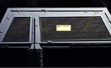
Moving onto the wings. I needed to add the half-round strips. I used .040" because that's what I had. The correct size is .030". So sue me. Anyway I drew a guideline to use as an approximation for placement.
From there I just started cutting and gluing. I would strongly recommend using reference photos and not the part map as a guide. There are a lot of subtle variations on positions of the rods that can get confusing depending on the angle of the photo. Also, I was able to create some nice miter joints by simply cutting pieces at an angle.
Before I knew it I was finished with one wing.
That's it for now. Hopefully by next weekend it will be heading off for primer. If you've made it this far, thank you. I appreciate everyone's feedback and support.


