You are using an out of date browser. It may not display this or other websites correctly.
You should upgrade or use an alternative browser.
You should upgrade or use an alternative browser.
4' (AKA 5 foot) Falcon build
- Thread starter RealDaveWinter
- Start date
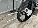
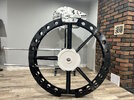
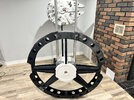
Some actual progress this long weekend. With all the parts on hand, I was finally able to finish up the radar dish. There are 2 or 3 parts that are to be applied after painting, but I'm considering this to be pretty much complete. I think a couple of the Hummel step parts around the skirt need to be cut, but I can take care of that after. All the Sealab parts are cast as are a couple of the Harrier parts.
Hopefully no major errors but if so, I will have to be live with it, as everything is glued down and it's tough to find some of the kits used in this area.
The lower part of the base will be detailed with the Shinano parts once it's in the hull and fixed.


Hopefully no major errors but if so, I will have to be live with it, as everything is glued down and it's tough to find some of the kits used in this area.
The lower part of the base will be detailed with the Shinano parts once it's in the hull and fixed.
You really don't appreciate how large these parts come out to be until you juxtapose it next to to something else, like that PG Falcon radar dish. This thing really is huge!
SB
SB
This is annoyingly perfect -- I keep looking for flaws, bit can't find any.
Want to build mine, if I send you the parts?
REALLY. NICELY. DONE.
I think the thing/part/sequence that scares me the most is the backside t-strut placements -- how did you mark those to know "exactly" where to put them? Will take all tips you can offer.
Want to build mine, if I send you the parts?
REALLY. NICELY. DONE.
I think the thing/part/sequence that scares me the most is the backside t-strut placements -- how did you mark those to know "exactly" where to put them? Will take all tips you can offer.
Thanks. Those T-strips are probably a bit too close together based on references, but I think they're more correct than what Bandai has on the PG Falcon. Really, I just used the standard MK1 eyeball and put them where I thought they were close.
I had to print 2 or 3 bases before I settled on what I believe is the correct size based on the placement of other parts.
I'm arriving at the point where I need to start thinking about painting and I've been going through options in my head for that. I've noticed on other people's builds they all prime in black (as ILM did) and paint over in white. I'll have to experiment with that and see what ends up working. Maybe I'll build up a couple of fake mechanical pits and some plating as a paint mule.
Can someone please confirm (or correct) these dimensions for the 8 mandible pits?
thanks

thanks
Regardless what published numbers you use, when building pit internals, it always seem to me that some tolerance was needed on the plus side.
Skin and armor thickness used in the build really counts when it come to determining pit ring wall depth. Appears as if every pit wall height has a specific “tallest” greeblie that will help determine this. When it came to floor diameter, there were cases for which some circumference locations required adjustment. Note mandible surface pipe fitting work has down comers that may require rolling a few piping elbows and adjusting T-fitting lengths to match pit equipment penetrations. Another way to say this is pit location and orientation is a function of mandible surface pipe runs.
Skin and armor thickness used in the build really counts when it come to determining pit ring wall depth. Appears as if every pit wall height has a specific “tallest” greeblie that will help determine this. When it came to floor diameter, there were cases for which some circumference locations required adjustment. Note mandible surface pipe fitting work has down comers that may require rolling a few piping elbows and adjusting T-fitting lengths to match pit equipment penetrations. Another way to say this is pit location and orientation is a function of mandible surface pipe runs.
Last edited:
There's a 1:24 Bandai M60 on eBay. Who's going to pull the trigger on that? 
Wow! I thought I got taken for a ride paying half that for mine!There's a 1:24 Bandai M60 on eBay. Who's going to pull the trigger on that?
A significant milestone today. All the 3D printed parts for the primary frame structure, are completed and assembled. The two aluminum tubes for the mandibles fit perfectly in their places.
I've photographed it standing in front of my 2 footer just to show the size difference. Once this is finished it will go in that corner where the 2 footer is now, and I'm not sure yet where that one will be moved to.
I had to revise my design a couple of times around the stern area but all in all, I'm happy with how it turned out. I can still lift the whole thing with one hand so weight wise it's okay. Most of its structural strength will come once the hull domes are glued in place. I designed it to be rather like a stressed skin aircraft wing and that seems to be working. The 3D rendering is of the top, the photos are of the bottom, which is why the central hub section looks different between the two.
I still need to go over it with a palm sander to remove the glue blobs on the seams. The balance is pretty much spot on as it stands upright on the curved portion of the stern with no issues.


She is a marvel of engineering beauty you have made there.
Just another WIP of a mechanical area. Still missing a few parts that are being cast but it's starting to look like a thing now. The original has quite the gap between the two M551 halves that I've tried to keep.

NICE rectangular cut-out on the M551. That cut took me at least three tries to get right.
So I'm hitting one of those parts of the build that requires some decision making - Accuracy vs Aesthetics.
As most everyone knows, the original Falcon model has a lot of areas that are not symmetrical. I'm currently working on the forward cockpit cone and you'll notice that the "window frames" are not the same sizes left to right. As viewed from this angle, the lower left frame is narrower than lower right, and upper left is wider than upper right. They're also not straight.
The OCD parts of me are in conflict because part of me needs this to be as indistinguishable from the original as possible, and the other part of me needs to make things symmetrical. Also because if someone looks at my build, and they were to see something that looks like this image, they'll think it's my mistake and poor modelling skills.
So I'm trying to decide how to go about things here.
I salute the OCD part of you. Here's my two cents:
GO FOR SYMMETRY.
You will utterly fail.
THEN, when someone notices that yours is not perfect either, tell them:
"I was recreating the exact imperfections of the original."
Win-Win.
GO FOR SYMMETRY.
You will utterly fail.
THEN, when someone notices that yours is not perfect either, tell them:
"I was recreating the exact imperfections of the original."
Win-Win.
