Ken, when I bought my kit from you for this saber, you gave me two choices of ball-catches. One of them had two screw hole tabs, and the other one had only one. Do you still have that pic somewhere?
You are using an out of date browser. It may not display this or other websites correctly.
You should upgrade or use an alternative browser.
You should upgrade or use an alternative browser.
More details on the Vader ROTJ saber - Please archive
- Thread starter Brevin Din-Shay
- Start date
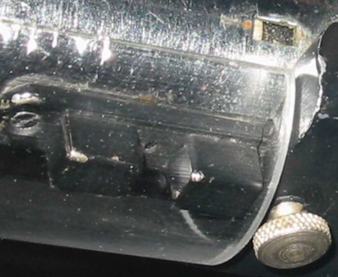
Profile of the ball catch from MOM:

fried mon calamari
Well-Known Member
James,
If that was for me, by profile I was refering to the putty/ shadow under the catch and more specifically the round spot next to the shroud. The overall profile is absolutely dead on.
Bad choice of words on my part, I think

If that was for me, by profile I was refering to the putty/ shadow under the catch and more specifically the round spot next to the shroud. The overall profile is absolutely dead on.
Bad choice of words on my part, I think
Brevin Din-Shay
Sr Member
</SPAN><TABLE BORDER=0 ALIGN=CENTER WIDTH=85%><TR><TD CLASS=$row_color>
James Kenobi 1138 wrote:<HR></TD></TR><TR><TD CLASS=$row_color>
Profile of the ball catch from MOM:
</TD></TR><TR><TD><HR></TD></TR></TABLE><SPAN CLASS=$row_color>
James (and everyone paying attention, for that matter) - compare the above pic with the one below. First of all, they are both at completely different angles, so it really makes it difficult to prove anything as far as the "new screw" is concerned.
Second of all, consider again how the "large" hole at the end of the saber is recessed. It's countersunk, so in this case James, your pic is helping by showing that there are no screws sticking above the door latch.


The middle screw, as tiny as it is, probably was countersunk as well...but nevertheless, it is there!
There's no other explanation for how the door latch can be held down.
(Edit - OOPS, repeated myself twice!
 Sorry for that, just did it again!)
James Kenobi 1138 wrote:<HR></TD></TR><TR><TD CLASS=$row_color>
Profile of the ball catch from MOM:
</TD></TR><TR><TD><HR></TD></TR></TABLE><SPAN CLASS=$row_color>
James (and everyone paying attention, for that matter) - compare the above pic with the one below. First of all, they are both at completely different angles, so it really makes it difficult to prove anything as far as the "new screw" is concerned.
Second of all, consider again how the "large" hole at the end of the saber is recessed. It's countersunk, so in this case James, your pic is helping by showing that there are no screws sticking above the door latch.
The middle screw, as tiny as it is, probably was countersunk as well...but nevertheless, it is there!
There's no other explanation for how the door latch can be held down.
(Edit - OOPS, repeated myself twice!
Johnleprekan
New Member

What we see as the hole in the upper left corner. In the right corner, it looks like a slot. Examine more closely and from a rotate your head or the picture a little and it turns out, it's just a hole that is somewhat deep. It looks like a slotted screw because of the perspective and lightning.
steveday72
Well-Known Member
[Shroud Cross Section]
Fried Mon / Kenny: Interesting what you pointed out about the shroud cross section being rounded on the inside edges. I haven't noticed that before.
I'm sure this piece is an item they picked up and used on the saber.
[Grip Damage]
Darf Vader: If the light colored area was metal and you can see the metal in that area when the camera is virtually parallel to it, then that means that the coating is very thin (otherwise it would be obscured by the sides of the damaged grip coating).
In other parts of the same image you can see fairly deep nicks and cuts to the grips, but these are black right through.
It's possible that the nicks and scratches have been painted in, however, because the main argument behind the large white/brown area being metal is that it shows rust, then that area would have been exposed to the air for longer than the small nicks and scratchs - so why wasn't that painted?
I can't see where you say that metal is showing through in the other (deeper) nicks and scratches?
Activator Band
When I was working on the 3D model, I did some calculations on the mid-band. I multiplied the outer tube diameter (1.5") by Pi, then multiplied the band diameter (1.5" + a thickness of around 0.03" = 1.56") by Pi and deducted this from the tube circumference. The result was that if the mid band was simply constructed from a sliced piece of 1.5" tube, then there would be a 0.1885" gap (around 5mm) between the open section when you wrapped it around the Graflex handle.
This shows that they constructed the mid-band from a piece of 1.5" tube. I can't see any coloring on the edges, but we know that on the underside there's a chip of paint that exposes a highly reflective silver metal, so it's probably stainless steel rather than chrome plated brass (we'll have to wait for a clear untainted image of the edge of the band before we can be certain).
[Ball Catch]
I ordered a bag of these from England a while back and on examination they are constructed in exactly the same way as they were back in the 1980's, when this prop was built. These ones don't have holes in the center, like the new photos show, but it could be a change in their design over the years.
Here is a photo of the ball catches from various angles (note that the back is hollow):

I looked quickly at the photo of what could be a screw in Photoshop, and I'm undecided one way or another at the moment. It does resemble a screw, but also resembles a hole that looks through the ball catch. The one thing that is odd that if it's a hole, then I can't understand why there is so much light in the back of the hollow ball catch - I don't think the camera flash could've illuminated it from that angle.
[Tire Valve/Recharge Port]
I'm 98% sure that what they used for a button/recharge port is in fact a universal clamp-in tire valve.
I did the research a few months back, but now better photos are available and to me, they show more clues that it's a tire valve.
On the hole that goes through the middle, it shows some signs of wear. The metal underneath can clearly be seen as brass - which is what they make tire valves out of, to avoid corrosion and spark issues.
Also, in that hole you can see a thread at the top. Now, I haven't managed to find a tire valve that has a thread all the way to the top, as the ones I've found only let you screw the valve core itself in from behind. This feature does help us verify when the correct part has been found.
Some people were skeptical of my tire valve theory, because they said the size of the hole was too small.
Here is a photo of a tire valve (rear/left) and a couple of nickel plated furniture parts (not what was used, but worth looking at). On my valve I've simply ground a bevel into the top of the hole, so that a) you can see the brass underneath, just like the original. and B) it has the appearance of being a larger hole, but is actually just a taper at the top (also just like the original).

Something I'd like to point out is that the tire valve I have here, like all the ones I've so far managed to find, have a higher angle and sharper bevel on the outside of the top flange. The photos of the original prop show that the angle is very slight and almost rounded from the flat part to the bevel.
Steve
Fried Mon / Kenny: Interesting what you pointed out about the shroud cross section being rounded on the inside edges. I haven't noticed that before.
I'm sure this piece is an item they picked up and used on the saber.
[Grip Damage]
Darf Vader: If the light colored area was metal and you can see the metal in that area when the camera is virtually parallel to it, then that means that the coating is very thin (otherwise it would be obscured by the sides of the damaged grip coating).
In other parts of the same image you can see fairly deep nicks and cuts to the grips, but these are black right through.
It's possible that the nicks and scratches have been painted in, however, because the main argument behind the large white/brown area being metal is that it shows rust, then that area would have been exposed to the air for longer than the small nicks and scratchs - so why wasn't that painted?
I can't see where you say that metal is showing through in the other (deeper) nicks and scratches?
Activator Band
When I was working on the 3D model, I did some calculations on the mid-band. I multiplied the outer tube diameter (1.5") by Pi, then multiplied the band diameter (1.5" + a thickness of around 0.03" = 1.56") by Pi and deducted this from the tube circumference. The result was that if the mid band was simply constructed from a sliced piece of 1.5" tube, then there would be a 0.1885" gap (around 5mm) between the open section when you wrapped it around the Graflex handle.
This shows that they constructed the mid-band from a piece of 1.5" tube. I can't see any coloring on the edges, but we know that on the underside there's a chip of paint that exposes a highly reflective silver metal, so it's probably stainless steel rather than chrome plated brass (we'll have to wait for a clear untainted image of the edge of the band before we can be certain).
[Ball Catch]
I ordered a bag of these from England a while back and on examination they are constructed in exactly the same way as they were back in the 1980's, when this prop was built. These ones don't have holes in the center, like the new photos show, but it could be a change in their design over the years.
Here is a photo of the ball catches from various angles (note that the back is hollow):
I looked quickly at the photo of what could be a screw in Photoshop, and I'm undecided one way or another at the moment. It does resemble a screw, but also resembles a hole that looks through the ball catch. The one thing that is odd that if it's a hole, then I can't understand why there is so much light in the back of the hollow ball catch - I don't think the camera flash could've illuminated it from that angle.
[Tire Valve/Recharge Port]
I'm 98% sure that what they used for a button/recharge port is in fact a universal clamp-in tire valve.
I did the research a few months back, but now better photos are available and to me, they show more clues that it's a tire valve.
On the hole that goes through the middle, it shows some signs of wear. The metal underneath can clearly be seen as brass - which is what they make tire valves out of, to avoid corrosion and spark issues.
Also, in that hole you can see a thread at the top. Now, I haven't managed to find a tire valve that has a thread all the way to the top, as the ones I've found only let you screw the valve core itself in from behind. This feature does help us verify when the correct part has been found.
Some people were skeptical of my tire valve theory, because they said the size of the hole was too small.
Here is a photo of a tire valve (rear/left) and a couple of nickel plated furniture parts (not what was used, but worth looking at). On my valve I've simply ground a bevel into the top of the hole, so that a) you can see the brass underneath, just like the original. and B) it has the appearance of being a larger hole, but is actually just a taper at the top (also just like the original).
Something I'd like to point out is that the tire valve I have here, like all the ones I've so far managed to find, have a higher angle and sharper bevel on the outside of the top flange. The photos of the original prop show that the angle is very slight and almost rounded from the flat part to the bevel.
Steve
lonepigeon
Master Member
Here's an idea.
Are we sure we have the correct catch?
Anyone see that stamped logo on the real prop?
I know the dimensions match up, but I bet we have a newer version minus the hole and an added stamped logo.
Like James said the hole has a purpose on the real part. The first catch found was the heavy brass one at www.mcmaster.com - It is exactly as James described. I still have one around here somewhere. It used to be pictured on PoSW.
If the prop builders added a hole they would've drilled a good size one and add a real screw - not a dinky one from an eyeglass repair kit.
They didn't go through alot of trouble to make this thing. What we see as overly complicated now was the quickest and fastest solution at the time. Detail never mattered on this prop. It was meant to be seen from a distance.
BTW- this wasn't the only saber for ROTJ. We just don't have the others nailed down yet.
miknugget
New Member
</SPAN><TABLE BORDER=0 ALIGN=CENTER WIDTH=85%><TR><TD CLASS=$row_color>
steveday72 wrote:<HR></TD></TR><TR><TD CLASS=$row_color>
Kenny,
It's good that by not relying on any previously calculated measurements, that we came up with the same results. It shows that the results are verifiable.
LOL "your feeble metric system".
...
Now, about the grips!
I went back to the photos and have found that the area that was thought to be a deep gouge, through the layer of plastic/rubber coating, and into the metal T track underneath ...well, it's not a gouge at all.
I compared it to another photo, which shows that same area and the white/brown patch of color is completely flat.
Then if you look at the areas that do have nicks, cuts and gouges in them (which are deeper than this white area), you'll see that they do not show any metal underneath.
Here's a comparison of the areas...

Steve
</TD></TR><TR><TD><HR></TD></TR></TABLE><SPAN CLASS=$row_color>
Is it possible that they did use beat-up/dinged metal grip material and painted over the damage?
I can see them getting man-handled while being cut up and shaped.
This "gouge" appears to me, to be a chip, but not from impact. Rather from the bend in that grip. The chip is right at the apex of the bend, when it was bent that little bit of paint delaminated and popped off.
That's what I see.

steveday72 wrote:<HR></TD></TR><TR><TD CLASS=$row_color>
Kenny,
It's good that by not relying on any previously calculated measurements, that we came up with the same results. It shows that the results are verifiable.
LOL "your feeble metric system".
...
Now, about the grips!
I went back to the photos and have found that the area that was thought to be a deep gouge, through the layer of plastic/rubber coating, and into the metal T track underneath ...well, it's not a gouge at all.
I compared it to another photo, which shows that same area and the white/brown patch of color is completely flat.
Then if you look at the areas that do have nicks, cuts and gouges in them (which are deeper than this white area), you'll see that they do not show any metal underneath.
Here's a comparison of the areas...
Steve
</TD></TR><TR><TD><HR></TD></TR></TABLE><SPAN CLASS=$row_color>
Is it possible that they did use beat-up/dinged metal grip material and painted over the damage?
I can see them getting man-handled while being cut up and shaped.
This "gouge" appears to me, to be a chip, but not from impact. Rather from the bend in that grip. The chip is right at the apex of the bend, when it was bent that little bit of paint delaminated and popped off.
That's what I see.
DARTH SABER
Master Member
well, I was just taking a good look at the pic posted several times above, and it seems to me that the prop dept chopped up this Graflex pretty good....Look at this-

(arrows on left) it looks like the seam that I pointed out earlier is not at the same plane level as the clamp band, but instead it sits higher! You can clearly see a step there..
The only think I can think of is that the prop dept cut the Graflex tube right above the grips (who knows why..) then inserted a tube inside the cut lower shell and added the black band on the inserted tubing..
(arrows on right) But, it looks as though the top shell does sit lower than the clamp...Im thinking that maybe the top shell goes some ways under the black clamp and then just ends..
I looked at other photos to see if the clamp angles at some point to indicate this, but the pics kindo of do and kind of dont show this...
Brevin Din-Shay
Sr Member
</SPAN><TABLE BORDER=0 ALIGN=CENTER WIDTH=85%><TR><TD CLASS=$row_color>
lonepigeon wrote:<HR></TD></TR><TR><TD CLASS=$row_color>
Here's an idea.
Are we sure we have the correct catch?
Anyone see that stamped logo on the real prop?
I know the dimensions match up, but I bet we have a newer version minus the hole and an added stamped logo.
Like James said the hole has a purpose on the real part. The first catch found was the heavy brass one at http://www.mcmaster.com - It is exactly as James described. I still have one around here somewhere. It used to be pictured on PoSW.
</TD></TR><TR><TD><HR></TD></TR></TABLE>
Do you mean this catch, Chris?

I realize the site is not the easiest to navigate, but if you have any specific one in mind, could you give us "directions," as in hyperlinks?
If the above pic is the one you are referring to, what does that prove? Just because the computer drawing there lacks both a hole and a stamped logo, that doesn't mean much IMO...it just means that it's a simple CGI.
<TABLE BORDER=0 ALIGN=CENTER WIDTH=85%><TR><TD CLASS=$row_color>Quote:<HR></TD></TR><TR><TD CLASS=$row_color>
If the prop builders added a hole they would've drilled a good size one and add a real screw - not a dinky one from an eyeglass repair kit.
</TD></TR><TR><TD><HR></TD></TR></TABLE><SPAN CLASS=$row_color>
In the words of the great and wise Yoda:
"Do not assume anything. . . ."
lonepigeon wrote:<HR></TD></TR><TR><TD CLASS=$row_color>
Here's an idea.
Are we sure we have the correct catch?
Anyone see that stamped logo on the real prop?
I know the dimensions match up, but I bet we have a newer version minus the hole and an added stamped logo.
Like James said the hole has a purpose on the real part. The first catch found was the heavy brass one at http://www.mcmaster.com - It is exactly as James described. I still have one around here somewhere. It used to be pictured on PoSW.
</TD></TR><TR><TD><HR></TD></TR></TABLE>
Do you mean this catch, Chris?
I realize the site is not the easiest to navigate, but if you have any specific one in mind, could you give us "directions," as in hyperlinks?
If the above pic is the one you are referring to, what does that prove? Just because the computer drawing there lacks both a hole and a stamped logo, that doesn't mean much IMO...it just means that it's a simple CGI.
<TABLE BORDER=0 ALIGN=CENTER WIDTH=85%><TR><TD CLASS=$row_color>Quote:<HR></TD></TR><TR><TD CLASS=$row_color>
If the prop builders added a hole they would've drilled a good size one and add a real screw - not a dinky one from an eyeglass repair kit.
</TD></TR><TR><TD><HR></TD></TR></TABLE><SPAN CLASS=$row_color>
In the words of the great and wise Yoda:
"Do not assume anything. . . ."
DARTH SABER
Master Member
heres a diagram which better illustrates what Im talking about-

Johnleprekan
New Member
That would be kind of strange since when you look at the part of the closer to the grips, you can see an open area where the two sides of the midband diverged. I'm trying to understand how it can be that the band is smaller around the grip area if that portion is eposed.
DARTH SABER
Master Member
</SPAN><TABLE BORDER=0 ALIGN=CENTER WIDTH=85%><TR><TD CLASS=$row_color>
Johnleprekan wrote:<HR></TD></TR><TR><TD CLASS=$row_color>
That would be kind of strange since when you look at the part of the closer to the grips, you can see an open area where the two sides of the midband diverged. I'm trying to understand how it can be that the band is smaller around the grip area if that portion is eposed.
</TD></TR><TR><TD><HR></TD></TR></TABLE><SPAN CLASS=$row_color>
Im still wondering the same thing...You can easily see that the part of the band closest to the emitter is on top of the tubing but the rear part of the band is sunken below the plane of the Graflex bottom shell
Oohyeah KL
Well-Known Member
OK, Brevin asked me to post this:
</SPAN><TABLE BORDER=0 ALIGN=CENTER WIDTH=85%><TR><TD CLASS=$row_color>
David wrote:<HR></TD></TR><TR><TD CLASS=$row_color>
"Many thanks to Barnstormer for his kind permission on
allowing us to view his grip template!"

</TD></TR><TR><TD><HR></TD></TR></TABLE><SPAN CLASS=$row_color>
Thanks, Barnstormer!! That's a very helpful diagram - thanks for sharing!
btw, I have one comment - I believe that the control box does not line up exactly between the two grips, but is slightly off, if anyone wants to get it 100% exact (though it will look like a sloppy job for those who don't know).
See here, for example:

</SPAN><TABLE BORDER=0 ALIGN=CENTER WIDTH=85%><TR><TD CLASS=$row_color>
David wrote:<HR></TD></TR><TR><TD CLASS=$row_color>
"Many thanks to Barnstormer for his kind permission on
allowing us to view his grip template!"
</TD></TR><TR><TD><HR></TD></TR></TABLE><SPAN CLASS=$row_color>
Thanks, Barnstormer!! That's a very helpful diagram - thanks for sharing!
btw, I have one comment - I believe that the control box does not line up exactly between the two grips, but is slightly off, if anyone wants to get it 100% exact (though it will look like a sloppy job for those who don't know).
See here, for example:
DARTH SABER
Master Member
</SPAN><TABLE BORDER=0 ALIGN=CENTER WIDTH=85%><TR><TD CLASS=$row_color>Quote:<HR></TD></TR><TR><TD CLASS=$row_color>interesting... it might in fact be, but this closeup shows a bright white edge between the midband and the bottom shell on the lower right, which seems to be in line with a white edge just peeking behind the grip int he middle of the photo. The "peeking" white edge defintitely belongs to the midband.
</TD></TR><TR><TD><HR></TD></TR></TABLE><SPAN CLASS=$row_color>
Yes it may be the edge of the midband casting that white line but also take into consideration that the band seems to be lifted up off of the inner tube a bit on this side...The band looks as though its lifted near the control box and then gradually tapers back tightly against the inner tube as it continues to wrap around to the other side..
The other photo (with my diagram) was taken from somewhere on the opposite side where the band seems to be tightly pressed against the inner tube.
obi1kenny
Sr Member
BALL CATCH (center hole)
I know I brought this up, but now I have switched positions on this subject.
I DO NOT believe that there is a screw in the center hole of the ball catch.
This pic shows why I think this way.
Going from a lot of different thoughts here, I have concluded that it is just a hole with no screw and here is why:
*They did this thing fast, yes no time to add a small little screw.
*The latch is hollow, yes if the latch we have today is the same as the older one then the screw would have to sit on top of the latch and it is clear that it doesnÂ’t. Now if we were to think it is a screw then we would also have to believe that the latch has a solid base and that would cause it to sit very different on the tube.
*I like the idea of the hole being there before the prop department got the screw, maybe it is the original design, maybe the carpenters that originally used it drilled it there so they could see the maker lines. Either way itÂ’s a good idea.
*One screw is not enough to hold it in place, well not really, the last conversion I did I only used the one screw with a nut underneath and it held great. I made sure that the hex bolt under the latch was countersunk far enough so that is did raise it up in the center. Also, from looking ate the pic above again, I DO think there is some glue at he cut off end, this would help keep it in place.
*Now again if we were to think that the base is solid, well it just wouldnÂ’t sit right on the tube, as the first one of these I ever built I used the solid brass ball latch that I ordered from McMaster. I had to machine it to look more correct. I radius milled the underside so it would sit flush. I cut off one end and that made it think it wouldnÂ’t sit solid enough so I drilled and countersunk a hole in the center (long before I knew there was a small hole there) and added an extra screw for support. Hey IÂ’m an engineer, I like to build things that are strong and can take a fall. Here is a pic that someone wanted me to post.
steveday72
Well-Known Member
Before anyone thinks that the ball catch is different and does have a solid base, I've constructed this image to show that they are identical in design and construction.

On the original saber, you can see the tabs of the bearing/spring housing go into the pressed steel base.
The ball catch on the far right of the image shows the tabs coming through from the front and that they are crimped to hold them in place.
Steve
On the original saber, you can see the tabs of the bearing/spring housing go into the pressed steel base.
The ball catch on the far right of the image shows the tabs coming through from the front and that they are crimped to hold them in place.
Steve
Just to add my .02 here
I have to say that I think the Bottom of the DV ROTJ saber is not from a real graflex. When I saw the saber at MOM, it clearly looked like aluminum to me. Now some have said that it appears dull because of glue. But in person it is clear that that is not the case. The bottom tube is ceratinly a different metal. If you want proof, look at the wholes between the grips. If this was a graflex bottom, the inside of the holes would be brass colored. But when you look at the wholes they appear the same color as the tube outer tube itself. Also, when I saw the saber at MOM, and looked at the wholes up close, they appeared to go deeper then would be possible on a graflex flash, meaning the aluminum tube that serves as a bottom for the saber might have a greater wall thinkness then a graflex.
My theory is that the bottom portion of this saber was made from a simple peice of pluming conduit, that had the bottom cut with a pipe cutter, which gives it the roled look, and a washer was placed in the bottom, glued in, and painted silver.
Dan Stokes
DDStokes@aol.com
fried mon calamari
Well-Known Member
Steve,
Those are good points on the catch. I think we can agree that it IS a hollow base. IMO the catch that we currently have is the one ( minus the hole). The hole in the middle also supports the hollow base idea since you can see the inner edge throught the hole ( middle arrow below).
Ken spelled out the screw theory with much better evidence than I did. I am still holding out on the hole just being a hole and the line is just a reflection of the lower lip.
Glue under the catch-
The arrow on the left points to what I think is a clear shot of something pressed up against the shroud and the catch.It looks like it follows the near edge of the catch a ways. You can see the reflection of the underside on the right and it looks different from the stuff up front

You can see it in this shot too. Here it looks like the stuff might even go up the side of the catch a little bit too ( which is also visible in the shot above )

IMHO this is what is holding the front of the catch to the tube.
Those are good points on the catch. I think we can agree that it IS a hollow base. IMO the catch that we currently have is the one ( minus the hole). The hole in the middle also supports the hollow base idea since you can see the inner edge throught the hole ( middle arrow below).
Ken spelled out the screw theory with much better evidence than I did. I am still holding out on the hole just being a hole and the line is just a reflection of the lower lip.
Glue under the catch-
The arrow on the left points to what I think is a clear shot of something pressed up against the shroud and the catch.It looks like it follows the near edge of the catch a ways. You can see the reflection of the underside on the right and it looks different from the stuff up front
You can see it in this shot too. Here it looks like the stuff might even go up the side of the catch a little bit too ( which is also visible in the shot above )
IMHO this is what is holding the front of the catch to the tube.
Similar threads
- Replies
- 181
- Views
- 10,510
- Replies
- 11
- Views
- 1,395
- Replies
- 9
- Views
- 3,392
- Replies
- 3
- Views
- 1,119