You are using an out of date browser. It may not display this or other websites correctly.
You should upgrade or use an alternative browser.
You should upgrade or use an alternative browser.
Let's Build An "Empire" AT-ST!
- Thread starter Boxcar Bret
- Start date
Exhausting!Wow...what an update
November 3, 2024
And we're back. I've been trying to crack the code on where the Thigh connects to the hip. There's a lot going on with only a few parts but once again, due to the limited reference photos it's nearly impossible to decipher what's going on.


Some of the parts identified on the existing parts map aren't what they appear to be which begs the question, "what are they?". Based off the people that I've asked that have built the model before, there is no clear answer. Everyone has either gone on their own path or based their approach off what others have done in the past.

Armed with this information, it's actually quite liberating. It comes down to the builders interpretation of what they're seeing.
Some things were obvious to me. Case in point, there's a rim from the C600 with a 8-rad rim inside. This rim is pretty common in the German wheeled vehicle kits so I imagine really any of them would work. The C600 rim needed to be sanded so the other rim could fit inside. Careful sanding with a Dremel made this happen.


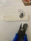
There seems to be a split consensus on whether theres a second C600 wheel that has been sanded down to a lower profile and inverted with an unidentified piece sandwiched between the two. This unidentified piece has a shape I've described as "oddly specific". Others have made this piece from scratch styrene. I decided to follow suit and made a template to the best of my abilities.


All of those parts are to sit on top of a Marder piece that is easily identified on the other side but I'm not sure that it was used on the "camera" side. There's just something funky about it. I don't know if it's been modified or what. What I did quickly discover is there's an order of assembly that became apparent when I began brining all the part together.
In an effort to make things clearer to me I added the modified Morser Karl piece to the equation. I trimmed the bottom edge so that it nested against the armature on the ribs of the part.


I spent the next couple of hours pushing this pile of parts into various configurations of layers and stacking, trying to come up with something that resembles what I'm interpreting in the photos, but something is getting lost in the translation for me.
If any of you that have built an ESB AT-ST have some insight, please share it with me and post pics if you've got them.
And we're back. I've been trying to crack the code on where the Thigh connects to the hip. There's a lot going on with only a few parts but once again, due to the limited reference photos it's nearly impossible to decipher what's going on.
Some of the parts identified on the existing parts map aren't what they appear to be which begs the question, "what are they?". Based off the people that I've asked that have built the model before, there is no clear answer. Everyone has either gone on their own path or based their approach off what others have done in the past.
Armed with this information, it's actually quite liberating. It comes down to the builders interpretation of what they're seeing.
Some things were obvious to me. Case in point, there's a rim from the C600 with a 8-rad rim inside. This rim is pretty common in the German wheeled vehicle kits so I imagine really any of them would work. The C600 rim needed to be sanded so the other rim could fit inside. Careful sanding with a Dremel made this happen.
There seems to be a split consensus on whether theres a second C600 wheel that has been sanded down to a lower profile and inverted with an unidentified piece sandwiched between the two. This unidentified piece has a shape I've described as "oddly specific". Others have made this piece from scratch styrene. I decided to follow suit and made a template to the best of my abilities.
All of those parts are to sit on top of a Marder piece that is easily identified on the other side but I'm not sure that it was used on the "camera" side. There's just something funky about it. I don't know if it's been modified or what. What I did quickly discover is there's an order of assembly that became apparent when I began brining all the part together.
In an effort to make things clearer to me I added the modified Morser Karl piece to the equation. I trimmed the bottom edge so that it nested against the armature on the ribs of the part.
I spent the next couple of hours pushing this pile of parts into various configurations of layers and stacking, trying to come up with something that resembles what I'm interpreting in the photos, but something is getting lost in the translation for me.
If any of you that have built an ESB AT-ST have some insight, please share it with me and post pics if you've got them.
November 9, 2024
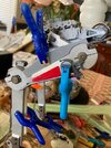
I'm still waiting for a the solution to the legs to reveal itself so I decided to have some fun with nipples! All the tubing under the head needed to connect to something. Some of the places of attachment were pretty obvious as they were predetermined by parts already glued to the head or torso. Others, not so much.
In the case of the three hoses coming from the back of the chin gun I used a F1 part with some brass wire inserted into it. I used the thicker of the black tubing found in almost all of the vintage Tamiya 1/12 F1 kits.

I found the clear tubing included in the same kits to be too thin. After doing some research I ended up using some Tamiya clear fuel line tubing I found on eBay. It was perfect because it was slightly thicker than the black tubing and has a matte translucent finish that looks right.

For the location of the mounting points I did my best approximation based off the photos out there. For the mounting points, or "nipples" I was pleased to discover that the F1 kits have a plethora of engine parts to be employed into service, many of which already have a mounting point for the tubing. Some had locating pins that served the same purpose while others were easily modified be inserting some brass rod.

Adding the tubing was a little fussy but was easier using tweezers.


I'm still waiting for a the solution to the legs to reveal itself so I decided to have some fun with nipples! All the tubing under the head needed to connect to something. Some of the places of attachment were pretty obvious as they were predetermined by parts already glued to the head or torso. Others, not so much.
In the case of the three hoses coming from the back of the chin gun I used a F1 part with some brass wire inserted into it. I used the thicker of the black tubing found in almost all of the vintage Tamiya 1/12 F1 kits.
I found the clear tubing included in the same kits to be too thin. After doing some research I ended up using some Tamiya clear fuel line tubing I found on eBay. It was perfect because it was slightly thicker than the black tubing and has a matte translucent finish that looks right.
For the location of the mounting points I did my best approximation based off the photos out there. For the mounting points, or "nipples" I was pleased to discover that the F1 kits have a plethora of engine parts to be employed into service, many of which already have a mounting point for the tubing. Some had locating pins that served the same purpose while others were easily modified be inserting some brass rod.
Adding the tubing was a little fussy but was easier using tweezers.
stevielewis
Sr Member
Excellent update! 


It is really looking incredible! As always, thank you for putting in the work making this thread.
Muzza
Sr Member
The plate you used on the inner thigh could I ask how you got that shape?View attachment 1876912
View attachment 1876913
View attachment 1876914
View attachment 1876915
View attachment 1876916
View attachment 1876917
View attachment 1876918
View attachment 1876919
View attachment 1876920
View attachment 1876921
View attachment 1876922
View attachment 1876923
View attachment 1876924
View attachment 1876925
View attachment 1876926
View attachment 1876927
View attachment 1876928
View attachment 1876929
View attachment 1876930
View attachment 1876931
View attachment 1876932
Sure. I saw it on someone else’s and I replicated it as close as possible on a piece of thin cardboard. I cut that out as a template and traced it onto some styrene. From there I just sanded it a little at a time until it was how I liked it. I’m sorry but I can’t remember whose it was.The plate you used on the inner thigh could I ask how you got that shape?
Muzza
Sr Member
I am building the Merlin models AT-ST and the moment and completing my scratch build one.Sure. I saw it on someone else’s and I replicated it as close as possible on a piece of thin cardboard. I cut that out as a template and traced it onto some styrene. From there I just sanded it a little at a time until it was how I liked it. I’m sorry but I can’t remember whose it was.
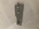
This is the one Merlin Models supply in their kit
Wow I’d say I did pretty good for eyeballing it. I couldn’t what the wide end looked like. Do you know what that long part with the hole in it is from?I am building the Merlin models AT-ST and the moment and completing my scratch build one.
View attachment 1880281
This is the one Merlin Models supply in their kit
Muzza
Sr Member
Not really but I am looking at all the model kits I have collected for the project, it looks like a part I have seen before, next thing is to go through all the tubs of parts I have and see if it is in there.Wow I’d say I did pretty good for eyeballing it. I couldn’t what the wide end looked like. Do you know what that long part with the hole in it is from?
thibkaji
Well-Known Member
Are you talking about this part?Wow I’d say I did pretty good for eyeballing it. I couldn’t what the wide end looked like. Do you know what that long part with the hole in it is from?
If so, that's from the Flak 36/37.
Hey, that’s it! Thanks!Are you talking about this part?
View attachment 1881134
If so, that's from the Flak 36/37.
View attachment 1881135
Muzza
Sr Member
No I was looking for the plate the parts are mounted to.Are you talking about this part?
View attachment 1881134
If so, that's from the Flak 36/37.
View attachment 1881135
Thank you for posting those pictures. The thigh part has been a challenge for me.Here is what I was working on over the weekend.
View attachment 1881267View attachment 1881268View attachment 1881269View attachment 1881270View attachment 1881271
Is this part from the Morser Karl?
Attachments
Muzza
Sr Member
I will have to check. if it was from the Karl.Thank you for posting those pictures. The thigh part has been a challenge for me.
Is this part from the Morser Karl?
Similar threads
- Replies
- 17
- Views
- 1,938
- Replies
- 5
- Views
- 786
- Replies
- 0
- Views
- 1,114

