September 11, 2024
Hey everybody. It's been a minute but that's not to say things haven't been going on behind the scenes. The last of the kits have been collected and I took a little break to refresh before jumping back into the game.
Since I'm still sourcing my armature, I decided to start working on the head. I used the schematic that's readily available and out "in the wild". It calls for the styrene to be 1.5mm but given that I wouldn't be vacuum forming it in two halves I went with 1mm.
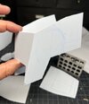
After printing the schematic out at actual size I cut out the patterns for the sides, top and front of the head and arranged it on the styrene.
Next was the matter of transferring the pattern to the plastic. If I had been just cutting out the pieces I would've dusted the backside of the pattern with Spray Mount, stuck them on, cut out the pieces and peeled of the paper while cleaning up the residue with Bestine. Since I wanted to include all the reference markings and guidelines I opted to use Saral artist's transfer paper. It's available in different colors for use on different color materials and comes in rolls or a sample pack.
I taped it to the styrene and then the pattern on top. From there it all about tracing everything with a mechanical pencil and compass. The results were pretty cool looking.
Cutting everything out was pretty straight forward with some light sanding to clean up the edges.
That said, let me give two pieces of advice that I learned as a designer for many years. First, when cutting a curve freehand with an Xacto, don't look at the blade when you're cutting. Your cut will be crooked or sloppy. Use the force and look past the tip to the line. Let your eyes trace the line and your hand will follow naturally. I know! Weird, right?! It takes a little practice but it's a mind blowing, game changing technique.
Second is DON'T BE STINGY WITH XACTO BLADES!!! Change your blade at the beginning of each work session and replace it frequently. Nothing will F-up a project or cut you quicker than a dull blade. They're expendables. Buy them in the 100 packs and go through them.
Although there's no panel lines to scribe, there are some rivet(?) holes on the sides that needed drilling out. I used an xacto to mark the pilot holes and then used a 1.34mm bit in a pinvise to carefully make the holes. In my enthusiasm I forgot that I was going to make the filming model version and drilled holes in both sides. (SPOILER FOR BRET: The filming model only has holes on the camera side.) These were filled in later after the discovery was made.
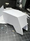
I started the assembly process by gluing two pieces together in one corner with CA and then tacking the rest of the joint with a couple of drops. This was so that if there were any adjustments the pieces could be easily popped apart. Once everything looked good I ran a small bead of CA along the inside seam and hit it with some kicker. I also dropped in a piece of angled styrene just to reinforce the seam.
I repeated this process until all four pieces were together. It's also worth noting that for the top I used .75mm styrene. In the reference photos the top looks thinner and I'm guessing that's due in part to the vacuum forming process.
I rounded off the radii of the mandibles with sanding sticks and snuck up on the curve. Likewise with the bevels on the bottom edges. Tamiya putty was used to fill in the seams and the holes drilled by mistake.
With the basic shape of the head completed it was time to start gluing the plating on. I used 1mm on the front and 2mm the top. The thicker piece needs to follow the curvature of the top and so I carefully bent it by hand to shape prior to gluing so as not to put strain on the thinner top piece. Two-part epoxy and clamps were used for the plating since it had a longer working time than CA and I could take my time aligning them into place.
Coming up next? Greeblie madness!