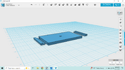
I started a test print on my 3D printer earlier this morning, 6 hours later I had the print ready.
What I did first:
- Imported into Blender
- Checked for "non manifold edges". There were some around the connection between what was modeled and the "back loops". Fixed it via the in-built tool (3D-Print add-on). Might also work without it
- Added a subdivision modifier with "Levels Viewport" and "Render" set to 2. Makes it look smoother without losing anything important
Printed it on my Ender 3 Max Neo with:
- PETG filament
- 0.2mm layer height (anything lower didn't seem useful for me here, as we don't have anything extremely detailed; my post-print process will take care of smoothing by sanding and using UV resin to make it super smooth)
- 999 walls! Well, this basically means that it's a solid piece of plastic, no holes inside as there is no infill
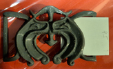
The result (worn with a narrow belt):
Front
View attachment 1899289
Side 1
View attachment 1899290
Side 2
View attachment 1899291
My opinion: don't think I'll need a pin at the back, it's already quite stable as it is (not shifting left/right). Obviously the height of the belt plays an important role here, my 3cm (I think) belt makes it look weird from the side. Will see if I can find a piece of carton that I can cut to 4.1 - 4.6 cm and see how it looks like with it.
Model is also quite sturdy, I'm not too worried about it breaking. Might still be worthwhile to strenghten the corners of the sides a bit
View attachment 1899294