"Mickey 17" (2025) - Memory Core / Dock / Case for The Human Printer

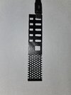
Here is a printed version of the Core Side Panel Grill. I probably should have checked the size earlier than this, but I included a USB-C cable as a reference. Again I am happy with the way the print turned out. Only a few stray "whiskers" on the back side. I printed this upside down to get the smoothest surface on the front. Of course, since things WERE going well, when I went to change filaments one of the printed parts which supports the extrude operations broke and I cannot unload the old filament. Since I built the printer from a kit I am comfortable with making the repair but now both of my 3D printers are down for different reasons. So members will not be pestered with any new prints in the near future - but I am working on some additional models. Just a fair warning. "If you do not want to see something - say something" - NOT New York Metropolitan Transportation Authority.
 

Attachments

  • Side Panel Grill.jpg
    Side Panel Grill.jpg
    1.7 MB · Views: 23
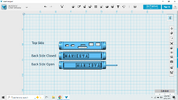
This model is my own extrapolation of the device contained at the top of the Core Storage Case. Only the top side is visible so I took liberties with the rest of the device. I have named this the Manikova "Meat" Sampler. Since even Mickey is concerned his "meat" might go bad after several prints, I thought there should be some quality control checks on the final product. The top side provides the output display. The back provides the sampling control. This is a slide which projects the sampling needle from it's protective housing and into the product. When the needle is retracted, the device provides its analysis. The movement of the slide will also change the appearance of the top side displays.

I have branded the device, with Alan Manikova's name, in a manner consistent with the side of the Print Bed (gurney). The debossed name on the slide surface again matches the gurney and provides a tactile surface to manipulate the slide. For those who want to produce any printed or labeled material, the best free font I found to match the gurney's style is a ttf called Universal Knowledge.

The slider has been sized to use the type of inflation needle for sports equipment such as a football or basketball.
 

Attachments

  • Manikova Meat Sampler.png
    Manikova Meat Sampler.png
    121.6 KB · Views: 21
Great progress! I love the design.

I assume you are going to mold a brick with voids, then remove the voids and insert these prints, correct?

Are you a print in different colors or print and paint person?
 
Yes. I plan to mold around a hollow shell which will be left in place. I am looking to have the main shell opening on the side, extend down to the front panel, and up to the handle opening. This will provide the space for electronics, wiring, and attachment for the exterior 3D prints. If things work out I will steal your idea of making this a practical device. The side panel will hold (up to) 5 USB thumb drives which I can use to connect to other devices via cables. I also reviewed a video clip audio where a technician placed the Core into the Docking Station and there is the sound of a hard drive starting up. There is definitely room for a laptop hard drive in addition to the USBs. I might use the "center square" opening in the side for that connection. With all those devices, the docking station will need to provide the primary power source via the Front connectors. The USBs of course can be powered by the attached device (laptop), and I may still want a rechargeable power source for the LEDs. However with line power I can put is some brighter LEDs.

I will be printing the external panels in different color filament. I believe I will use Light Gray (Chrome/Silver), Black, and maybe a Dark Gray, like a Graphite color (which I do not yet have). I would like to not paint the prints. My thought is that this planet's operations probably cuts corners and goes with the "lowest bidder" for their equipment to support "expendables". So if those devices are a little rough, like the Core itself, that fits the plan. For other objects, like the Printer and Lab equipment, the opposite seems to be the case. Since those probably support management and non-expendables, that equipment is new and clean. Since I assume the Docking Station might not be just for Mickey; it falls into the second category -the IBM Beige as mentioned is some of the behind-the-scenes articles and interviews.

I have not started the Docking Station as I want to first understand how I want to use it with the Core. Also, I like 3D printing when there are details which might be difficult to create using other techniques, or they are of the size to fit on a print bed. The Docking Station design is very clean, and very angular. Well suited to just flat-sheet plastic modeling. There is the gray panel on the docking front which I probably will 3D print (to match the Core). That panel has an oblong "button" in the center I hope to use as a "release" control. As mentioned before I would like the Core to "click" into the dock, and so depending on the mechanism I may need/want a practical release.
 
Not stealing. I'm putting this all out in the ether for all to enjoy.

That said, been crazy busy with work, but want to share what I've got in case it helps your efforts. STEP and F360 files for the Cradle. It appears you are using an AutoDesk tool, so this might work.

Fusion 360
STEP

Screenshot 2025-04-16 at 5.45.19 PM.png
 
caross, I was able to import your design with no problems. My version of the Autodesk software (123Design) was free and is about 25 years old - I know it has not been supported for at least eight years - but it still does most of what I need. I have used Fusion 360, but it takes me about twice as long to accomplish anything because I just have not become familiar enough with the user interface.

I modelled the interior shell for my Core which will be molded around and left in place. The first illustration is the rough shell form. Both the Right Side and Front will have an opening to the outside Core surface (which is actually shown "covered" in the illustration). I then modelled a 2D sheet metal template to fabricate the shell. I know Fusion 360 has an entire component to do this which would have saved me time - but it was an enjoyable exercise in 3D spatial manipulation. Since I do this for my own enjoyment the journey is more fun than the result. The second attached file is a 3/4 scale template only because it will fit on an 8.5 x 11 inch piece of paper. Anyone wanting to do something similar should definitely make a paper template, cut it and fold it so they know their design is accurate. I normally add different BLUE fold lines for the proper "mountain" and "valley" fold orientations but I got lazy. I also realized I did not include the holes for the handle.

The shell itself will be made from very thin aluminum used for flashing on roofs. This is thinner than the metal used for duct work. It is easy to cut and bend. Once the shell is formed and riveted together I will seal the seams with silicone caulk. I will then insert wood blocks to plug the the side and front openings. Since the metal is so thin when filling the form without the blocks it would deform these critical areas and make it more difficult to use 3D printed covers. The plugs are simple rectangles. The side is 25 x 100 x ~88.75 mm (going all the way to the left wall to support it). The front is 50 x 75 x 15 mm. The exterior form has the inside dimensions of 215 x ~102.5 x 65 with holes for the Handle. A wooden dowel plug will be inserted to produce the void for the handle. The exterior form will be made from wood with an open top, assembled with exterior screws so it can be disassembled after molding to remove the Core. The interior walls of the form can be textured and provide protrusions which will produce the major indentations on the exterior of the Core. There will also be screws from the outside to hold the Side and Front plugs in place to ensure the shell is aligned with the exterior of the Core. The dowel Handle plug will also help with alignment and support the weak sides of the shell.

I am starting to think about the material for the Core itself. Clay is still my first choice but since it does not "flow" it will be a multi-part fill operation. Fill and tamp the bottom in the form. Then add the shell. Add a new wooden plug (75 x 35 x 176 mm, with a hole for the handle) inside the shell to support the sides during the fill-and-tamp process. Fill and tamp the sides up to the top of the shell/plug. Remove the handle and interior plug, add a loose metal top. Caulk it in place? Add a "mostly pre-formed and tamped top" and tamp it into place to ensure a good bond ONLY with the Core's outside clay walls.

Alternatively, I am wondering if colored Plaster of Paris would work? It would flow better but some of the same techniques above may still be desirable to avoid voids. But only the exterior surface is critical.

I hope this two person dialogue expands to a larger audience with more feedback and ideas.
 

Attachments

  • Core Shell.pdf
    178.3 KB · Views: 20
  • Core Shell Template.pdf
    114.6 KB · Views: 21
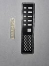
Main printer repaired - now ready to print the broken part for printer #2. I was anxious to see if things were back together properly and I did a test print without any new calibration. Side Grill from before the breakdown fitted perfectly into the new untested bezel print. A new Manikova slider needs more work on my settings. And I will now do the proper calibrations and First Layer Print Test.

On similar note I often bemoan the amount of time it takes me to dial-in the settings on a new 3D model or new filament. Today I was reminded that is nothing compared to the WORK and time required to fine-tune a fifty-year-old table saw. In the last half-century designers HAVE made some things easier to use.
 

Attachments

  • Side Bezel and Grill.jpg
    Side Bezel and Grill.jpg
    1.4 MB · Views: 20
Back
Top